Batmobile
March, 2016
Overview
The two main goals of the Batmobile project were:
- Follow a line using the camera at the back of an Android phone.
- Look stylish while doing so.
All the CAD files and software for this project can be found here.

Hardware
I designed the body, wheels, motor mount, phone mount, and bat light using browser based CAD software. I used Eagle to design the PCB.
Body, Wheels, and Mounts
The body is made out of laser cut plywood.


The wheels, mounts, and bat light were all 3D printed with PLC.

The image on the left below is the mount to hold the drive motors in place as well as the motor that turns the bat light. It attaches to the base of the body. The right image is the mount to hold the phone in place. This slots into the hole in the base. The rest of the hole in the base is to allow for vision of the floor.


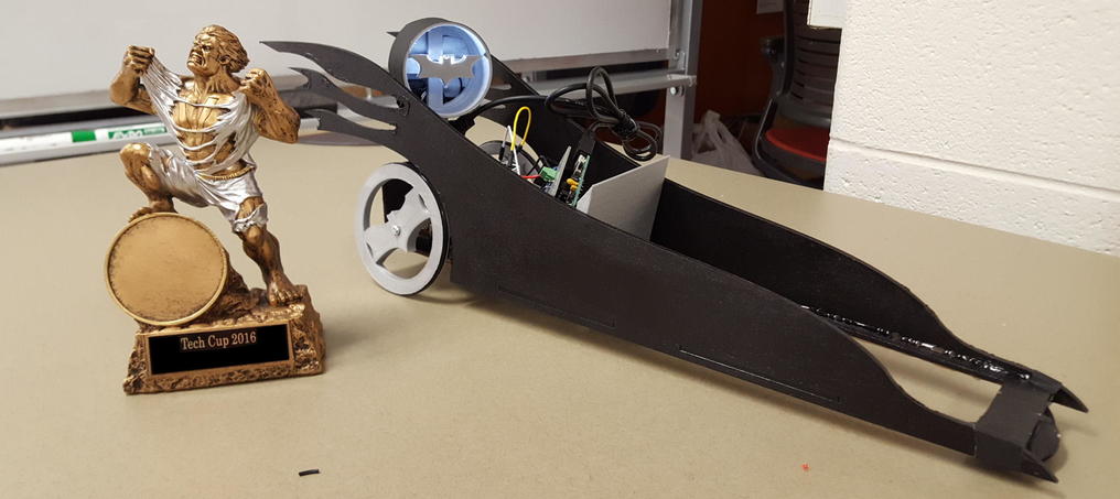
Bat Light
The bat light is attached to a motor at the back and rotates as the batmobile drives. There are two white LEDS behind the bat so it can cast out the bat signal.

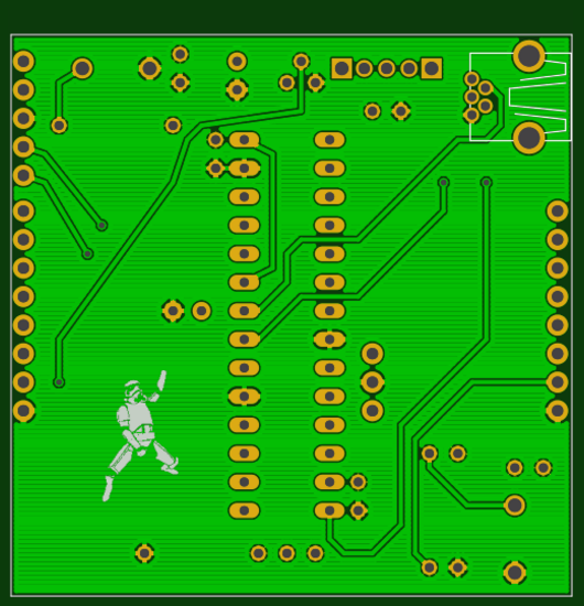
Printed Circuit Board
I designed the PCB below to hold the PIC32 microcontroller that I use to communicate with the android phone and drive the motors accordingly.

Software
C code
The C code is to program the PIC32 microcontroller to communicate with the android phone and then send the right control commands to the h-bridge circuit driving the motors.
Android App
I designed the android app to have the following graphic interface:

The grey block at the top shows the image coming from the camera. The first 3 sliders are there to control the levels of Red, Green, and Blue that are filtered from the image. This way a specific coloured line can be tracked and the system can be easily adjusted to follow a different line if necessary. The 4th slider controls the height in pixel value of which row on the image is being searched to find the line.
The BATMAN button at the bottom is there to start playing the Batman theme song when it is pressed.