
MYHOG Racer
February, 2016
Abstract
MYHOG racer stands for Myo Controlled Hemispherical Omni-directional Gimballed Racer. It uses just one hemisphere as a drive force. With the hemisphere constantly being spun and making contact with the ground, the gimbal’s tilt allows drive in any direction. Because the drive force is a hemisphere, the more it is tilted, the greater the radius between the point of contact with the ground and the central axis of rotation. As a result speed can be easily controlled. (More information can be found here). The Myo is an armband worn just below the elbow of the driver. It uses a combination of EMG, IMU, and accelerometer signals to achieve machine trained gesture recognition that allows the driver speed and direction control of the MYHOG.
Hardware
The Frame
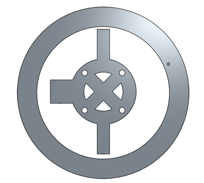
The frame is made out of 1/8 inch thick plywood. I used a laser cutter to carve out the design. This made it easy and quick to re-cut any pieces that were needed.


The base of the frame and the upright housing the servos, are each 3 pieces of plywood stuck together with wood-glue and screws. The two supporting pieces (one upright with “MYHOG” carved on it and the joining top piece) are both two pieces of plywood thick. I created the design for these pieces using the free online software, “OnShape”. The STL files for each part can be found here. The different pieces of the frame are designed to fit in firmly with each other.
At the other end of the frame, I originally attached two caster wheels for support. Since the first iteration I have changed to using ball bearing wheels instead. This allows for better omni-directionality. I have also spread the wheels a bit further out from the centre to help support the frame a bit more.

The Gimbal
The gimbal attaches right between the two poles of the upright piece that houses the servos.

The gimbal is made up of two 3D printed pieces. (STL files found here). The inner piece has the motor attached and rotates about a longitudinal axis (roll) in the MYHOG’s forward direction. This allows for forward or backwards drive. It is driven by the bottom servo. The outer piece rotates about a lateral axis (pitch) in the MYHOG’s forward direction, allowing the MYHOG to steer left or right. It is driven by the top servo. At the moment the servos are connected to the gimbal pieces using small wooden rods. Each rod has a hole in both ends to enable a threaded wire to attach and still allow enough flexibility for rotation. With testing I have found this allows too much play and thus instability. Different materials will be tried in further models.
Motor Connection and Hemisphere
The hemisphere is a racquet-ball ball with the top cut off. I 3D printed the piece below to attach to the motor on the one end and fit inside the racquet-ball ball on the other.

I then filled the hemisphere with glue from a glue gun. Allowing the glue to cool down and harden, secured the motor connection piece in place and solidified the hemisphere.


Electronics
Motors
For the drive motor I used a brushless DC motor built by XXD called the A2212 KV1400. It weighs 47g , draws a no-load current of half an amp, and has a KV rating of 1400. I connected it up to a HW30A ESC for control.
The two servo motors are HI_TEC’s HS_755HB with a weight of 110 grams and a torque rating of 13.2 Kg-cm. These are more than powerful enough to provide the required torque to turn the MYHOG’s gimbal.
MYO
The Myo is an armband worn just below the elbow of the driver. It uses a combination of EMG, IMU, and accelerometer signals to achieve machine trained gesture recognition.
Communications
The Myo communicates using a Bluetooth protocol and a USB plug and play adapter that I had plugged into my laptop.
The micro-controller I used is the PIC32MX795F512H. The PIC32 is using a NU32 development board designed at Northwestern University.
I serially sent the commands from my laptop to the PIC32, using a couple of Xbee modules with self assembled break-out boards from Adafruit.
Both the NU32 and the Xbee were left plugged into a breadboard for ease of development. Further models of the MYHOG would include its own dedicated circuitry.
Power
The NU32 and Xbee module are running off a 5V regulated supply from a 9V Duracell battery situated just infront of the breadboard. The two servos run off a different 5V regulated supply from a 12V LiFePO4 battery pack with a capacity of 1500 mAh. It is capable of safely supplying 4A. The brushless DC motor also runs off this supply, but with an unregulated voltage. For convenience I have two of these battery packs so that one can charge while the other is being used. They have a 5.5x2.1mm male barrel connector which make them easy to swap in and out of the MYHOG which has a female connector right next to the battery case at the top of the frame. (Further models of the MYHOG might see that casing moved a bit lower for better weight distribution and more stability.)

The Software
Myhog Ros Workspace
For receiving data from the Myo, I use a ROS package called ros_myo. From this package, the raw data from the Myo is published under three topics: myo_imu, myo_emg, and myo_gest. The myo_emg topic publishes a custom message containing the signal readings from the Myo’s eight EMG sensors. For use with the MYHOG, I subscribed to the myo_imu and myo_gest topics which publish standard IMU and standard UInt8 messages respectively. In my subscription node, I convert the IMU quaternion to Euler angles and then use these to determine an appropriate PWM duty cycle to send serially through the Xbee to the PIC32. This controls the servos. I also send an on or off PWM duty cycle to start or stop the drive motor based on the trained “fist” gesture.
For ease of use when testing and potentially playing with the MYHOG, a node that subscribes to a joystick has been added. This node also allows varying speed control of the drive motor (as opposed to just on/off when using the Myo).
PIC32 C Code
The code used to program the PIC32 can be found here. I chose to use Timer 3 on the PIC32 out of the 5 that it has available and set it to run at a frequency of 50Hz (For use with all three motors). The PIC32 has available output compare pins of which I chose to use OC1, OC2, and OC3 for those familiar with the PIC32’s structure. The servos output angles are varied using a pulse between 1ms – 2ms. The drive motor is controlled through the esc. It is turned off with a pulse of 0.72ms and turned on with a pulse width of 1.24ms.
Testing Videos
Future Work
- Redesigning the frame slightly to help improve the stability of the MYHOG.
- The design and printing of some dedicated circuitry for the MYHOG’s electronics as opposed to leaving everything on a breadboard.
- Adding some feedback using an IMU on board to help stabilize direction control.
- Adding machine trained gestures on the Myo that correspond to different preprogrammed actions with the MYHOG. For example, putting up only one finger makes the MYHOG go into clockwise circle mode.